Why A Loop?
MW DXers have been using loops for years. However, with the huge increase in noise within the home, they’ve been beset my noise and have fallen into disfavour. SW DXers have traditionally used outdoor antennas but many DXers now find space restrictions as well as noise levels to be an issue. The answer could be a coax (a.k.a. a magnetic) loop.
Hams have been using magnetic loops for receiving and transmitting for decades. They have the advantage of being very compact and much quieter than conventional antennas, can readily be used inside and they’re directional.
This article will be mostly practical, a wee bit of theory is required to help you understand why they are so quiet. Signals (including noise) take two forms, a magnetic form and an electrical form. The non-magnetic copper outer sheath of a coax loop will pass magnetically-formed signals through the outer shield onto the inner conductor. However, electrically-formed signals (e.g. local noise) will be conducted to earth via the outer braid. In reality, a coax loop will still pick up noise but very importantly the signal-to-noise ratio will improve, making the signal you want to hear stand out in strong noise.
Being directional, they can be rotated to peak a signal or to null noise.
Loop Size
The loop’s circumference is derived from the formula 300/F x 0.084 = c, where F is the freq in MHz and C is the loop circumference in metres . So a loop for 12MHz is 300/12 x 0.084 = 2.1m, which seems more accurate based on the loop I built. By adding the variable capacitor, it can be tuned as low as 3MHz. Bill Marsh has been experimenting with a loop for MW and in particular, the X-band and found the resonant point for the X-band (1600-1700kHz) after experimentation. The magic circumference being 8.8m. Bill used 3 turns on a 2.93 circumference, 0.933m diameter former.
The more capacitance you add to lower frequency, the more efficiency and gain drops so you may need to use a low-noise preamp. I’d suggest building a bigger loop to suit a lower optimum frequency. In the example above with the 3-gang variable capacitor and both switches on, a 2m circumference loop will tune from 12MHz down to 3.0MHz. The variable capacitor I used was scrapped from an old valve radio though you could use a single-gang variable if you’re happy with less band coverage.
Another option is to fit aerial plugs to both ends of the coax and have interchangeable loops for different bands. Or you can nest two loops, one inside the other each with their own tuning system.
Construction
Materials:
Coax (see text below)
2 x glands/grommets to suit the coax
2 x small switches
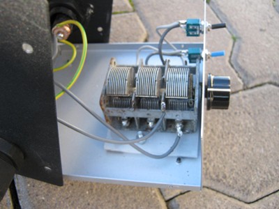
1 x variable capacitor (3-gang air-spaced if possible)
1 x knob to suit above
1 x SO239 or other antenna socket
1 x enclosure to suit
1 x former or frame to support the loop
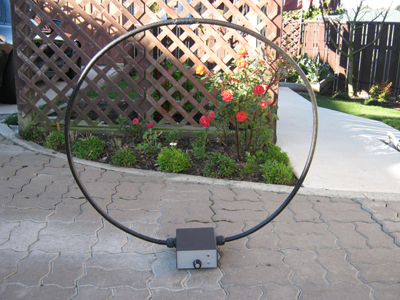
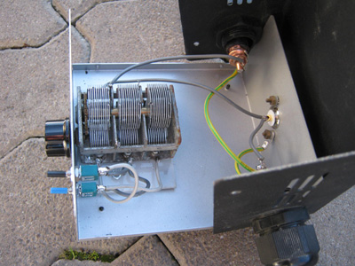
The shape of the loop can be circular, square, triangular, diagonal or any other shape. In the top photo example, I’ve used rigid coax which supports itelf. Once you’ve cut it to size you MUST create a braid-beak. Find the exact middle of the loop and a strip away a 20mm length of outer plastic sheath and remove the same amount of braided wire and or foil, leaving only the centre wire and it’s insulation. Finish the braid-break by taping over the break.
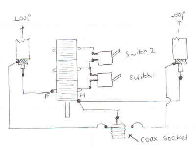
The connections to the variable capacitor are marked ‘F’ and ‘M’. ‘F’ are the fixed vanes, and there is usually a nice tab for you to solder to. ‘M’ are the moving vanes, the connection point is usually a tab on the body of the capacitor (the top wire below).
 Use good quality coax with 100% braid coverage, the 75 Ohm stuff used for Sky/Freeview with a braided wire outer and foil inner shield is inexpensive. Rigid 50 Ohm LMR400 or LDF450 is more expensive but great for smaller loops (2m or less) with no need for additional support. It doesn’t matter if you use 50 or 75 Ohm cable.
The variable capacitor, switches etc can be enclosed (metal or plastic is fine) or left open. If you use metal, insulate the variable capacitor from the box.
Kelvin Brayshaw has used cheap hula hoop from The Warehouse is a good former for a 2m circumference loop. Flexible electrical conduit could also be used as a former for smaller loops, e.g. 1.5m or smaller.
Bill Marsh has also been building coaxial loops and has made one primarily for the X-band. Read the article here.
I’m going to use magslab, a 5mm x 150mm think covering used to protect buried cables. It could be cut into strips of a suitable width. Short left-overs could be obtained from any electrican/lines company that uses it to protect buried cables.
Using The Loop

The loop in action, sitting on the dining room table.
The loop can be connected to your radio by a coax lead or, if the radio has a ferrite rod simply by sitting it beside the loop. You may need to turn your radio at right angles to the loop, depending on where the ferrite rod is.
You will need to retune the variable capacitor often as these loops have a narrow bandwidth.
Some improvements may be worth trying. A cheap “lazy susan” turntable from a kitchen ware shop could make a handy rotator. The loop output impedance is around 10 Ohms so a 4:1 impedance matching transformer may improve performance (5:1 and 6:1 aren’t easy to wind or purchase).
Find an electrically quiet spot in or around your house and have fun!
Many thanks to fellow “looper” Kelvin Brayshaw for his help. Here is Kelvin’s article as published earlier in the DX Times and on radiodx.com
Here are some other builds:
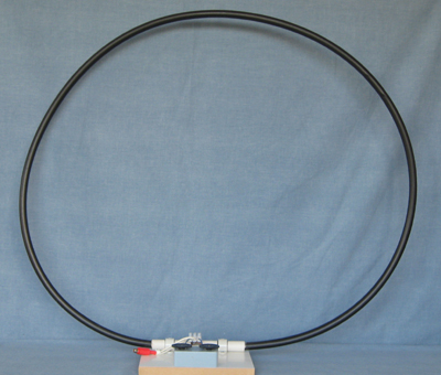
Kelvin Brayshaw’s loop using LMR400 coax and electrical conduit fittings.
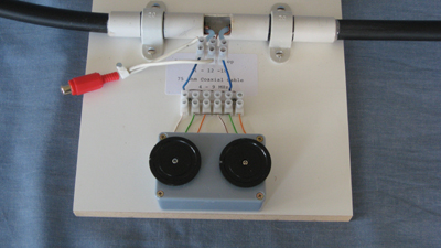
Close up of Kelvin Brayshaw’s arrangement. Kelvin has used two single-gang variable capacitors and jumpers to change the tuning range.
Thanks to DL8YHR. This loop is for the 160m ham band.
Hex loop from Pinterest