X-BAND LOOP 1
This article was written by Bill Marsh (Jnr) in July 2015.
Because I live in a town house with limited space for aerials, I decided some time ago to experiment with loop antennas. Initially I built a normal 40 inch box loop which was very unstable in windy conditions and altogether too flimsy for outdoor use. Recently I was recently reminded that “Magnetic Loop Antennas” were a more sensible choice of loop antenna for today’s noisy environment as by their very construction reduce considerably electrical interference without compromising radio signals.
With this in mind I set out to design and build a coaxial loop antenna. The internet is full of useful and not so useful articles on this subject.
I used the following criteria for my loop:
- It had to be able to be mounted outside and rotatable as there was no room indoors for a loop. Besides my wife would have a fit if I set one up in our craft/hobbies room.
- The loop needed to match a 50 ohm coaxial feed-line as my receivers had 50 ohm inputs.
- The loop needed to be remotely tuned.
- As I envisaged I may need a mast-head amplifier, it’s power supply needed to be remotely switched off to provide good battery life.
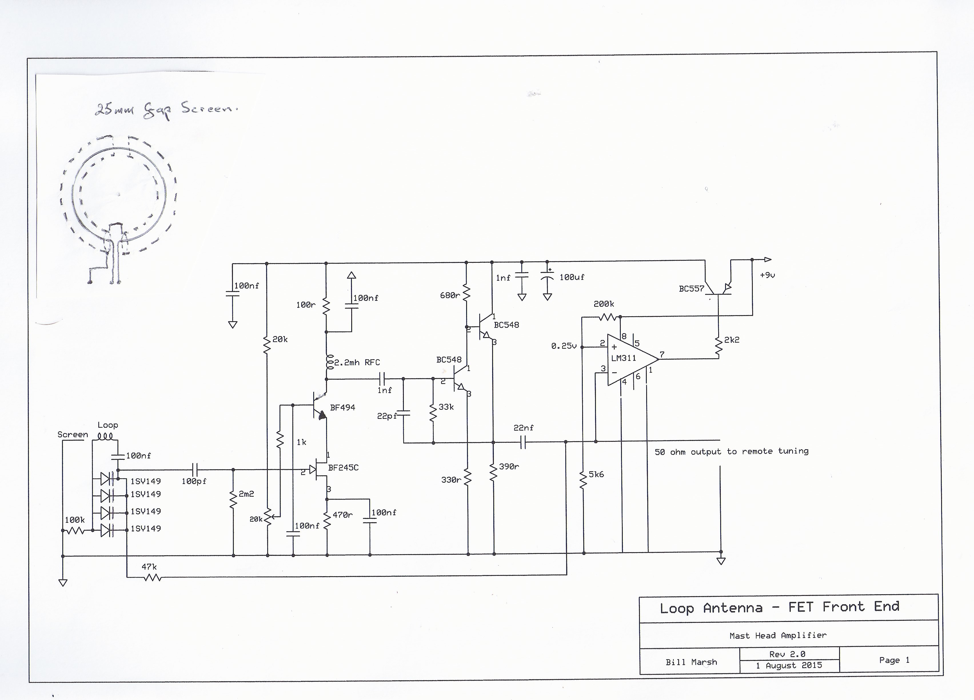
With the above in mind I set out to build my first loop. I happened to have a piece of RG58 coax spare that was 8.8 metres in length. I had decided to make my loop 3 turns. The type of loop chosen requires that 25 mm of the outer shield be removed at the exact mid-point (in my case at 4.4 metres) [see appendix below] by carefully cutting and removing so as not to compromise the inner conductor and insulation. When the coax is coiled into 3 turns this places the braid break directly opposite the loop feed point. The feed point is brought into an aluminium box for termination to feed line (or amplifier) and this box also contains the tuning diodes. My prototype loop uses a plastic box rather than aluminium with little or no compromise in shielding from electrical noise. I experimented with matching transformers between loop and coax feeder with mixed results and decided to use an FET preamp. The preamp has advantages in that it eliminates the need for matching, does not load the loop (with resultant drop in frequency) and provides some gain which eliminates any signal loss in the feed line with some extra left over for those weaker receivers. Initially I thought my 8.8 metre loop was resonating at 1.75 Mhz but since adding the preamp I have found that it is resonating at about 2 Mhz. For optimum results it is best to have the loop resonate at the top end of the frequency range of interest, namely 1.7 Mhz in my case. Although the loop is performing exceptionally well and picking up stations on the X band, getting it right will be corrected with the construction of loop number 2. This is the first time I have heard a station on the X Band at this location.

The design of the pre-amp follows pretty conventional lines except that I decided to use two FET’s connected in cascade. This has the advantage of low noise, stability and isolation between input and output. This is followed by two general purpose transistors configured as buffer and 50 ohm output. I have used 4 tuning diodes connected in parallel and this allows this loop to tune the full broadcast + X band. The tuning range for the diodes is 1 to 8 volts and this tuning voltage is feed up the coax feeder from the remote control unit. It is noted that the minimum capacitance of each diode x four sets the upper frequency of the loop.(I may find this is too much with loop number 2 and some switching in and out of diodes may be required to tune up to 1.7 Mhz.) To enable the preamp to be switched off remotely I have employed an LM311 voltage comparator and switching transistor. The reference voltage for the comparator is set by a resistor divider at 0.6 volts. When the tuning voltage is less than this reference voltage or the power switch on the remote control unit is switched off then the power to the preamp is interrupted. There is some small current drawn continuously by the comparator. The preamp is switched on over the tuning range of the diodes.
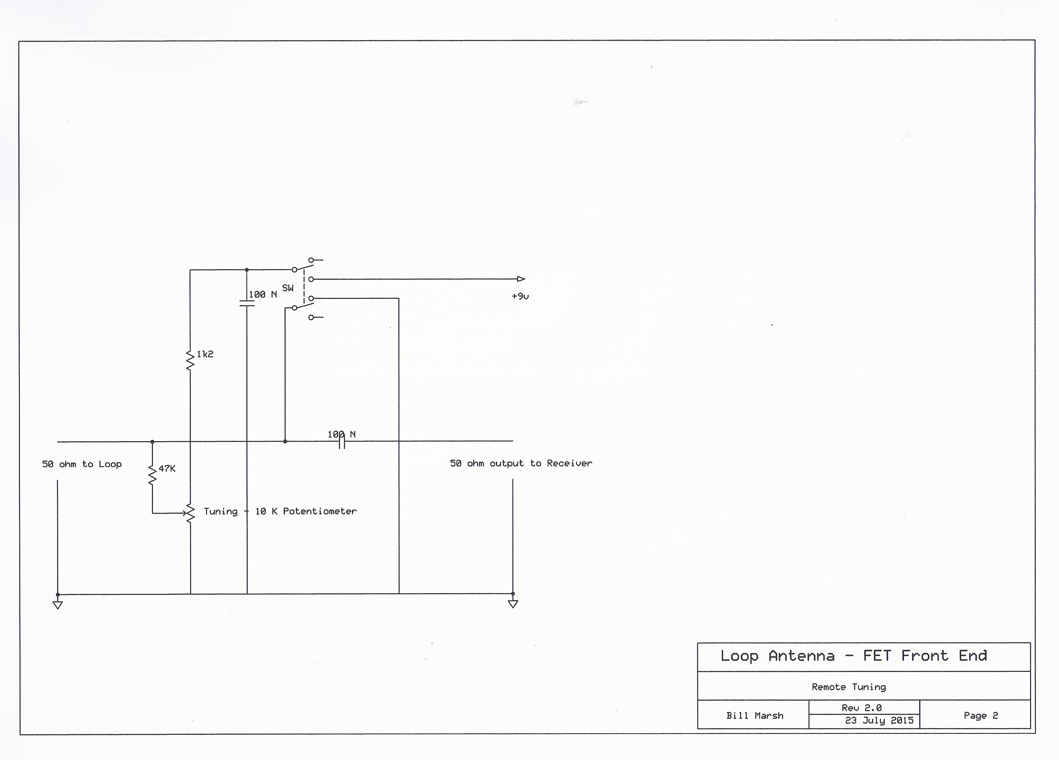
The remote tuning unit is merely a potentiometer for tuning, a battery source and switch for the tuning diodes. A blocking capacitor is installed to block the tuning voltage coupling to the receiver input. Care is needed when placing the bypass capacitor so as not to attenuate signal.
Related Article: Coax Loop Project
Appendix:
X-BAND LOOP NUMBER 2
The construction of Loop Number “1” (see below) was successful but left a number of unanswered questions regarding design criteria to be resolved. My 8.8 metre length of coax was resonating above 1.8 mhz and it became apparent with more research that it should resonate close to the highest frequency of interest, in my case 1.7 mhz for optimum performance. This meant a longer length of coax. It must be remembered that this type of loop can only tune down in frequency by adding capacitance to lower the resonant frequency. It is not possible to tune to a higher frequency. I was guided by the formulae used by Kelvin Brayshaw i.e 300/freq in Mhz x 0.084% = metres of coax. The ARRL quote a multiplier of 0.085%. It became obvious that this formulae possibly only works with a single turn loop. In my case I was making a 3 turn loop and at a lower frequency. Other factors were having an effect on the resonant frequency of the loop, were the velocity factor of the coax and the additional inter-turn capacitance. With a 3 turn loop as I lowered the resonant frequency this multiplication factor also reduced to close to 0.062% when I finally reached the ideal length of coax.
The following outlines my steps toward the end result.
I had a piece of 18 mm Heliax which was 13 metres in length. When I coiled this into 3 turns it resonated at 1.7 Mhz. This has become my radio workshop antenna and resulted in the dismantling of my wire antenna strung around the section. My valve radios are now hearing signals not possible on the external wire antenna due to electrical noise pickup. The loop is near my workbench (outside and hidden between garage wall and fence) Very short wires come through the wall to a 3 gang tuning capacitor and a rotary switch to select 1, 2 or all 3 sections of the gang.
I had bought a 15 metre length of freeview type cable to experiment with. When I coiled this into 3 turns it resonated at 1.49 Mhz. I next coiled this 15 metre length of coax into a 5 turn loop and it resonated at 1.12 Mhz. I then decided to space the 5 turns by 1 wire diameter. As the overall diameter of this coax cable is 8 mm I decided to use a length of 9 mm nylon rope as a spacer which is slightly spongy and as a result gives a good uniform spacing between the turns. This moved the resonant frequency up to 1.35 Mhz.
At this stage I decided to abandon the idea of a 5 turn loop in favour of a 3 turn loop. I also concluded it was only necessary to check the resonant frequency of the loop as any loop can be tuned down in frequency by adding capacitance.
My starting point was to go back to my 15 metre length of freeview type cable and progressively reduce the length by 1 metre at a time. In order to keep the braid break central to the loop this meant cutting half a metre from each end of the coax. As the coax was shortened my garden edge support had to be reduced in circumference. With 15 metres the circumference of each turn is 5 metres.
The results of each change are as follows:
15 metres close spaced gave a resonant frequency of 1490 khz,
15 metres 1 x diameter spaced gave a resonant frequency of 1660 khz,
14 metres close spaced gave a resonant frequency of 1530 khz,
14 metres 1 x diameter spaced gave a resonant frequency of 1730 khz,
13 metres close spaced gave a resonant frequency of 1590 khz,
13 metres 1 x diameter spaced gave a resonant frequency of 1800 khz,
12 metres close spaced gave a resonant frequency of 1630 khz,
12 metres 1 x diameter spaced gave a resonant frequency of 1910 khz,
11 metres close spaced gave a resonant frequency of 1750 khz,
11 metres 1 x diameter spaced gave a resonant frequency of 2200 khz,
After 3 changes in length it was apparent that results were following a straight line graph and that frequency could be easily determined.
For my purposes I have decided to make my loop 3 turns using 11 metres of coax close spaced. The reason for choosing close spacing is that I intend to enclose the loop inside 25 mm PVC electrical conduit. 25 mm being chosen for ease of threading the coax into the loop and also for the strength available with this diameter conduit. This loop is approximately 1.16 metres diameter. This loop also appears to be much more sensitive than my loop number “1” probably due to the larger diameter and greater capture area.
Anyone contemplating making a loop along these lines should be aware that not all 3 gang tuning capacitors (ex old valve radios) are equal. The minimum capacitance is the critical factor for these loops and any capacitor chosen must have the lowest capacitance possible when the plates are fully unmeshed. A number of the older variable capacitors had quite high minimum capacitance due to the way they were manufactured. Some of the last variable capacitors manufactured had very low minimum capacitance and also quite high capacitance when fully messed. Those which have the fixed plates supported on ceramic mounts generally have low minimum capacitance, typically 8 pico farads. It is this minimum capacitance that sets the upper frequency limit of the loop. One way around this is to aim for a slightly higher resonant frequency when choosing a length of coax. You should also consider that different types of 75 ohm coax may give different results to those above due to differing capacitance values per lineal metre. It is therefore suggested that you start with a slightly longer piece of coax than needed, and progressively shorten each end equally until you get the desired result. Obviously any permanent supporting frame comes last when the final circumference of the loop is known.