 On the recommendation of ace DXer Paul Ormandy, and with practical assistance from Ray Crawford and Sutton Burtenshaw, I finally commissioned 2 EWE antennas in November 2007. Paul had made up the required parts for me some time before, but as something of a technophobe, it needed a couple of technically competent radio amateurs armed with soldering irons to get me going! Last month I commissioned a third EWE by myself and now feel able to confidently recommend this antenna to others.
I think it’s called a EWE because the antenna configuration is an inverted U shape. The first person to describe the EWE was an American radio amateur Floyd Koontz (WA2WVL) in 1995. The antenna wire itself runs down each mast, and is earthed at each end. Most importantly, it must have a preamplifier to deliver a worthwhile signal, along with a weatherproofed balun (matching transformer) at one end, and a weatherproofed variable resistance (potentiometer) at the other.
I am very fortunate to have plenty of space for antennas, and a location relatively free from man-made interference, but I understand that the EWE will work well in noisier urban locations too, helping reduce TVI and other interferences. However it is important to keep the antenna as remote as is possible from metal buildings, gutters etc.
EWE antennas can be constructed to varying lengths and heights, such as 3 metres high and 7.5 metres long, but I am very pleased with the dimensions Paul recommended – 5 metres high, 15 metres long – to suit both medium wave and shortwave DXing. The dimensions chosen for the antenna, the preferred listening range, and the ground conductivity at your location will dictate the resistance value (I’ve seen recommendations ranging between 800 Ohms and 1000 Ohms, so a variable pot. is the best approach).
Indeed the most difficult aspect of constructing my EWEs was tuning the pot to the optimal setting for medium wave DX. I’m told I should tune it for a null or most reduced signal from a station ‘off the back-end’, but here in Northland there isn’t really a candidate to the west or northwest. I’m waiting for really fine weather when I can take the radio out to the pot location and then try and tweak it whilst listening to a few different stations within a hundred kilometres of my location.
My hope with the EWE was that it would give me improved DX on medium wave. They have certainly done this, but with the added bonus of outperforming all my other antennas (100 metre BOG (beverage on ground) longwires and a 20 metre long Alpha Delta Sloper SWL antenna (purchased from Universal Radio USA) on shortwave as well! In particular, the tropical band frequencies – below 6 MHz are much better received on a EWE.
Here’s my component list:
-
2 antenna masts 5 metres high (I was lucky to have some lengths of Oregon timber). You can use longer e.g. 7m poles and bury two metres if you wish to avoid guywires, or drive steel stakes into the ground and lash 5m poles to the stakes)
-
Guy wires and insulators to support these masts.
-
Insulator at top of each antenna mast (as my poles are wooden, I use Screw-In Electric Fence Insulators made by Gallagher.
-
25 metres of insulated Antenna Wire (5 metres up, 15 metres across, 5 metres down) 1.0 – 2.5mm electrical appliance wire is fine.
-
2 Earth Ground Rods (mine are Earth Peg ECDR12 – 1800 Utilux Earth Stake Copper Clad purchased from J.A.Russell Ltd last October for $15 each plus GST).
-
2 Earth Clamps (for Earth Rod attachment), from J.A.Russell Ltd, about $5 each.
-
Matching Transformer (Balun) in waterproof container, constructed for me by Paul Ormandy. Paul can be contacted at zl4pw@orcon.net.nz or snail mail – 13 Swift Street, Oamaru.
-
Variable Resistance (Potentiometer) in waterproof container, also constructed by Paul Ormandy (contact details above).
-
Length of Coaxial Cable (50 or 75 ohms) for lead-in wire to run from Balun at front of antenna (remember that lead-in runs from the ‘front end’ of the antenna).
-
Broadband Pre-Amplifier. Mine came recommended by quite a few EWE ‘farmers’ and is made by Advanced Receiver Research, Box 1242, Burlington CT 06013, USA. Their model AR² P0.5-30/20VD has a bandwidth of 500kHz to 30mHz, that is medium wave and shortwave. Cost is US$55.00. Check out the “Broadband LF Preamplifiers” page atwww.advancedreceiver.com/
-
12 volts DC power supply for the pre-amplifier.
A bit of cost overall, but I think the results of the EWE antenna are worth a whole lot more! I only have to look at the quality logs in my logbook over the past 9 months for the proof!
Bryan Clark (with valuable assistance from Paul Ormandy)
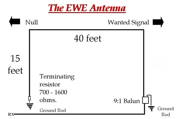
Dimensions are variable, 3 times as long as high, e.g. 3 x 9 x 3m, 4 x 12 x 4m, 5 x 15 x 5m. 3 x 9 x 3m work well down to the lower SW bands and 4 x 12 x 4m works well down to MW.
Fig 1. Diagram of EWE Antenna
Messrs Ray Crawford, Bryan Clark and Sutton Burtenshaw instal the EWEs at Mangawhai
Fig 2. EWE Erecting Team – Ray Crawford & Bryan Clark (standing), Sutton Burtenshaw (front).
Fig 3. Some EWE components – left to right: AR² broadband preamplifier, weatherproof balun (matching transformer) by Paul Ormandy; weatherproof variable resistance by Paul Ormandy, Electric fence post Insulator, Earth Clamp.