Aerial and Earth Systems
By “Starlite”
From the 1948/49 “Lamphouse” Annual
The early pioneers of radio were once faced by a very serious problem. Their crude attempts at transmission were being held up as the range achieved was extremely limited. Someone got the bright idea of suspending a piece of wire in the air. Thus the aerial was born. The earth was the logical conclusion. Radio transmission and reception experiments increased in efficiency.
The same holds good today.
Too many people are satisfied that their modern receiver rolls ‘em in with “only a bit of wire dangling down behind the cabinet, y’know!” It would pay them to consider just how much their reception would be improved with a decent aerial and earth attached to the appropriate terminals so thoughtfully supplied by the manufacturer. The manufacturer did not supply aerial and earth connections just to be in the fashion. They are there simply because a good aerial and earth system Is necessary to any set, with the exception of portable receivers which are designed and so fitted to operate with their own built-in loop aerial.
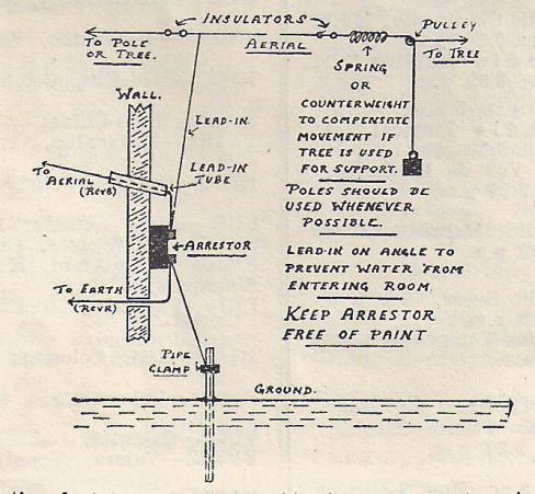
A satisfactory general-purpose aerial consists of a hundred foot coil of wire . . . single or multi-strand, pure or tinned copper, covered or uncovered . . . three or four insulators, a lead-In tube, a lightning arrestor and an earth clamp. The installer uses sufficient wire from the coil to run from the earthing point proper to the appropriate terminal on the receiver. The balance of the wire, usually approximately 80ft. in length, is used for the aerial. The sketch shows a conventional L type aerial suspended between two supports. The average height of the supports should be about 30ft. The connections are shown pictorially.
A water-pipe, provided it makes an early entry into the ground, makes quite a good earth, but if the plumbing system wanders for a few hundred yards around underneath the house, then scrap this idea. Obtain 6ft of pipe, drive it into the ground at the handiest point, leaving a few inches protruding above ground-level, attach the clamp and wire, connect the free end to the set and there you are. Water poured into the pipe in dry weather moistens the adjacent ground thus making a better earthing contact. Any earth wire Is NOT insulated. Any lead-in wire is ALWAYS insulated.
If you have an old copper or car radiator handy, these two articles make good earths. Either article is as good as the other, but the radiator has certain advantages. Its filler cap can he left above ground for easy filling. Holes punctured in the body allow the water to seep into the surrounding ground. With a buried copper, the bowl is placed Into a hole after a few holes have been pierced in its body and the object is covered with earth. When the copper Is half covered, a piece of spouting is placed vertically over the centre of the copper and the filling-in completed. Water is poured down the spouting in dry weather, with the same effect as in the case of the car radiator. Don’t forget to solder your earth wire to the object before burial.
Theoretically, an earth should be as long as the aerial and buried directly below it along its length. Marconi transmission aerials are usually installed in this fashion, and, although it may seem a hard task, it is liable to pay dividends if you are interested in D.X. with small receivers.
If an L aerial does not lend itself to the geography of your home, then a T aerial can be erected. A T aerial describes itself. The lead-in takes off from the centre of the aerial proper. The L type has it’s lead-in running from one end. Any type of conventional aerial is directional to the point in which it runs from the lead-in end.
Thus the T serial is directional to two points 180 degrees apart. A doublet aerial is directional to a point broadside to its length.
Any aerial should be clear from obstructive elements such as trees, buildings or large metallic objects. I have never lived next door to a gasometer, but I should imagine that things, speaking from the purely radio point of view, would not be too pleasant.
As regards doublet aerials, there are many of these on the market, and are principally designed to reduce inter-actional noises, such as interference from commercial machinery or apparatus. The same applies to noise-reducing aerials which are designed to reduce unwanted noises which are introduced by a normal aerial system, the same as doublet aerials. Designers of doublet aerials usually have their eye on the improvement of short-wave reception as well as noise reduction, while other types of noise-reducing aerials follow a normal T or L type, but Include, as in the case of doublet aerials, the usual R.F. transformers at the point of lead-in contact at the aerial proper and also at the receiver end. The T or L noise-reducing aerial, unless otherwise stated, is a general purpose aerial. The lead-in for a doublet aerial is twisted or transposed, while the lead-in for the other type is shielded metallically, and the shield grounded to a separate earth.
If a tree or trees support your aerial, one end should be sprung or counterweighted, so that the movement In a breeze is compensated in order that the wire does not snap.
Periodically, your aerial should be lowered and carefully overhauled. The Insulators should be washed with soapy water to remove the grime and any soldered joints critically examined. When erecting your aerial, try to eliminate soldered joints. The lead-in tube should be examined for cracks and other manifestations of deterioration. It should be replaced if it will not pass inspection. The same applies to the lightning arrestor. A faulty arrestor will cause no end of unwanted noise.
The earth should also receive the same careful examination, for a corroded connection at the clamp often causes you to think that there is a lot of static about.
Careful erection and subsequent attention to your aerial and earth pays dividends. Never share an aerial with another listener.